
Bubbles, boundaries, sandboxes, isolation
Part 1: A forever story of securing running code.
What’s in a sandbox anyway?
A sandbox, for computers, is the concept of protecting a process or set of processes from … other processes. OK, we all know this, to some degree.
A bit of history first
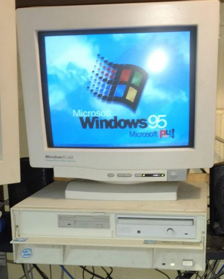
A long time ago, operating systems were using shared memory, a.k.a. “cooperative mode”. These systems would run on computer hardware which lets you address any memory you like, at any time. It was simple, but difficult to keep reliable when running multiple programs from multiple vendors at once, that never talked to each other: programs would write over each other despite their best efforts, and crash the machine. Some of you may remember Windows 95, MacOS Classic (9 and below) and so on: they’d crash all the time.
To solve this, all process memory is virtualized, and every process thinks it has access to “all the memory”. This can be virtualized in different ways, but the most common is just called paged virtual memory. This is where memory is decided in equal-size blocks and pages can be allocated, moved around without much intervention from the process, other than requesting or free memory as needed. It is a set of features that is usually called protected mode. The memory management unit for the CPU is called just that, MMU. This allows the CPU and operating system to ensure that no program can overwrite another program’s memory directly, without the kernel and CPU’s agreement (e.g. by declaring shared memory zones).
This post mainly references Intel-specific terminology. The concepts are fairly similar, though not always the same between different CPU vendors and architectures.
The CPU knows this by dividing the execution within privileged levels called rings:
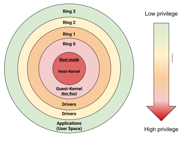
- Ring 3 is used for regular processes, programs, etc. Your web browser runs in ring 3.
- Ring 1, 2 are normally reserved for device drivers.
- Ring 0 is the most privileged and this is where the boot code, kernel code runs.
- non-root mode is where the kernel and regular kernel(s) run.
- root mode is where the virtualization code runs - sometimes called “Ring -1” as it can manage the kernels.
- Usually, there is also a System Management Mode (SMM) which can suspend code in Ring 0 root mode, sometimes called “Ring -2”
- Sometimes, Intelligent Platform Management Interfaces (IPMI, i.e. remote management) are called “Ring -3“ as they can override SMM and all other rings.
This ensures, for example, that code executing in Ring 3 cannot override another process’s code (it’d need to go to Ring 0, or request the kernel to do something on its behalf in Ring 0).
Note that the protected mode also includes other features such as task preemptibility, which allows the CPU to stop executing a process’ instructions and do something else, so no single process can “keep the CPU for themselves”, otherwise any process that occupies the CPU would cause a denial of service (which did happen in Win 95 and friends: the OS would then appear “frozen” - micro freezes were very common, just like crashes!).
Boundaries
These rings are boundaries, or what I like to call “bubbles”. The privileges are different between each bubble, and you need to break through the other bubble somehow to get its privileged. With rings, you could say that ring 0 is sandboxed from ring 1, which is sandboxed from ring 2, then ring 3, by the CPU.
Communication (between boundaries)
As indicated, a process in Ring 3 may need to access a privileged action - say the command kill needs to remove another process from memory: it can’t, it has to ask the kernel, which runs in Ring 0, to free the memory. This is done through a communication channel, usually called IPC for Inter-Process Communication, RPC for Remote Procedure Calls or Syscalls for System Calls for example (Call Gates / SYSENTER/EXIT on the CPU).
Want to know more? Read about Page management, x86’s Global Descriptor Table, MMU and System calls. OSDev.org and kernel.org have great all-around documentation on system architecture in general, which is well worth reading.
The case of hardware I/O
Hardware devices (GPU, sound card, etc.) also communicate over a bus, which, to simplify, also connects to the system memory (RAM) and the CPU. Access to the system memory is gated by a controller called IOMMU for Input-Ouput Memory Management Unit.
IOMMU translates (virtual) memory addresses to real memory addresses and thus controls and protects memory from devices having direct memory access. When an IOMMU is not present, it is not possible to properly protect or isolate access to the hardware’s memory (i.e. it’s shared direct memory access).
“Hardware” virtualization/hypervisors
OK, so we have protected memory and memory access is controlled and well-managed. Code that is privileged runs in an isolated Ring, and there are ways to communicate between them. Visually, it’s like a bunch of bubbles that have special communication paths to travel from one bubble to another one. What does virtualization have to do with this?
For virtualization to be fast, the machine’s hardware isn’t fully emulated. Instead, things are tracked and near-direct hardware access is granted. This means the MMU and IOMMU need to understand, to some degree, which virtual machine (and its kernel) is running “where” and what memory it can access. This is done with a Hypervisor such as KVM (running in Ring 0 root mode, while the guest kernels run in ring 0 non-root mode) and a CPU supporting virtualization instructions (instructions to tell the CPU what processes are in which virtual machine and so on). On Intel, this CPU functionality is called VT-x, and supports direct device access through VT-d for Virtualization Technology directed I/O access.
Without MMU and IOMMU, it would be impossible to arbitrate memory access correctly, so these are key components when using virtualization.
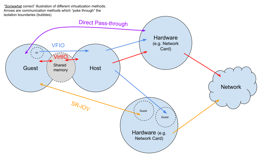
For example there is VFIO on Linux, which translates calls to allow for user-space (Ring 3) drivers - this is especially useful when IOMMU is supported (VFIO with noiommu allows for direct memory access, so, breaks part of the isolation model, in other words, good IOMMU hardware support is required). Intel also provides good documentation if you’d prefer a deeper dive.
More similar to VT-x and also providing virtual functions, some devices now support Single-Root Input-Output Virtualization (SR-IOV). It is a slightly newer method that provides additional isolation functions to the PCI-e bus - this allows sharing access to devices without direct pass-through while retaining good performance. It allows an IOMMU to understand which memory should be allowed by which virtual machine for PCI devices.
Finally, VirtIO emulates devices in software, this is slower and communicates between host and guest using shared memory, though it also allows to “move” IO interfaces from one piece of physical hardware to another since it does not depend on a physical IOMMU, direct memory access, and so on.
All these methods allows “pocking through” the isolation boundary in different ways:
Summary
So, that’s my largely simplified TLDR of how isolation works with a CPU, be it through virtualization, or between processes. At the end of the day, you have an isolation boundary (bubbles) and specific ways to access and communicate data between these bubbles. What’s important here, is how these bubbles are defined (rings, hardware memory partitioning, etc.) and what can be communicated between them.
See you in part 2!
Comments